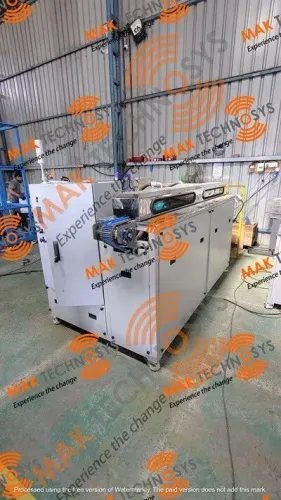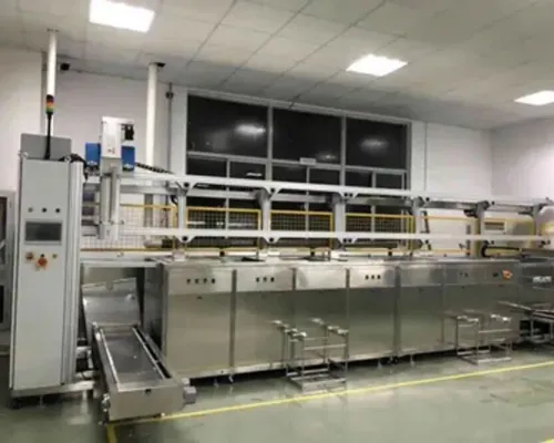
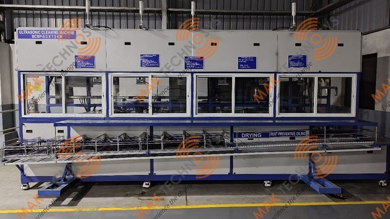
Production cleaning is not just an ultrasonic tank: the machine must move parts through solvent contact, cavitation, rinsing, drying and transfer without reintroducing oil or leaving solvent behind. By following each station and setting frequency, solvent, temperature, filtration and validation criteria through trials, you can judge whether a proposed system will deliver repeatable cleanliness.
Key takeaways
- Follow the basket through loading, cleaning, rinsing, drying and unloading.
- Match solvent and temperature to the contaminant, material and drying requirements.
- Compare effective ultrasonic power, frequency and coverage instead of nominal wattage.
- Use documented cleanliness tests to separate process failures from handling contamination.
What happens to a component from loading to unloading
A programmed transfer system moves the basket or fixture between sealed process stations, so cleaning depends on the complete sequence rather than the ultrasonic tank alone. If you are asking “how solvent based automatic ultrasonic cleaning equipment for works,” follow the component from its loading position through each controlled handoff.
1. The operator loads parts into a fixture that keeps surfaces exposed, prevents contact, and allows solvent to drain from blind holes. Overloading creates acoustic shadowing and traps air, leaving shielded areas dirty.
2. The machine lowers the fixture into a pre-clean or immersion tank. Solvent circulation loosens loose oil and carries particles toward filtration before ultrasonic energy is applied.
3. The fixture enters the ultrasonic tank for a programmed dwell. Transducers generate cavitation while the solvent moves around exposed faces, recesses, and internal passages.
4. The system lifts and drains the load, then transfers it through a solvent rinse. Drain time limits dirty solvent carryover into the next tank.
5. A vapor-degreasing stage or heated immersion rinse removes remaining oil film when the specified solvent and part geometry suit that stage. The controller stabilizes the vapor zone before exposing the parts.
6. The machine dries the load with controlled vapor condensation, heated solvent evaporation, vacuum, filtered air, or a combination. Drying must remove solvent from holes and joints, not merely the visible faces.
7. The transfer mechanism returns the dry fixture for unloading or passes it to the next process. The solvent ultrasonic cleaning process is complete only when cycle timing, drainage, solvent condition, and final dryness meet the production specification.
How cavitation removes contamination from complex surfaces
A blind hole can remain dirty even when the exposed face looks bright because cavitation only works where liquid reaches the contamination. Transducers mounted beneath or around the tank convert generator output into alternating compression and rarefaction waves in the solvent.
During rarefaction, local pressure falls below the solvent’s vapour pressure and bubbles form. They collapse near the component, producing microjets and shock waves that break the bond between oil films, particles and the surface.
This action reaches recesses that brushes cannot enter, but it will not reliably remove cured coatings, strongly bonded oxides or chemically resistant deposits without a suitable solvent and dwell time.
Generator frequency controls bubble size, collapse behaviour and penetration. Lower frequencies produce more forceful cavitation for heavy contamination; higher frequencies create smaller bubbles that can enter finer features with less aggressive impact. More electrical watts do not guarantee better cleaning, because acoustic output also depends on:
- Transducer position and tank geometry
- Liquid level and acoustic coupling
- Frequency stability and electrical-to-acoustic efficiency
- Part spacing and shadowing
Solvent movement carries loosened contamination away and replaces depleted liquid at the surface. Dense baskets, nested parts or trapped air in a blind hole block that exchange, leaving quiet zones where cavitation falls sharply. Fixtures must expose critical faces, keep parts apart, allow drainage and provide an escape path for air.
Qualify industrial ultrasonic cleaning equipment with representative parts or a defined test coupon. Measure residue at the hardest-to-clean location; nominal watts per litre cannot prove cleanliness.
How to choose solvent, temperature and cleaning stages
Combine immersion cleaning, ultrasonic cleaning and vapor degreasing when each removes a different failure mode: immersion dissolves bulk soil, ultrasound reaches recesses, and vapor degreasing displaces the final liquid film. Use only the stages your soil and geometry justify; extra stages add solvent carryover, maintenance and exposure-control demands.
| Stage | Main action | Use it when |
|---|---|---|
| Immersion | Soak and recirculate solvent | Parts carry heavy oil, chips or loose soil |
| Ultrasonic immersion | Cavitation plus solvent contact | Blind holes, threads, slots or trapped contamination need agitation |
| Vapor degreasing | Condensing vapor rinses and dries cooler parts | You need final film removal and low liquid carryout |
In a solvent based ultrasonic cleaning equipment line, pre-clean immersion protects the ultrasonic bath from rapid soil loading. Follow with ultrasonic cleaning, a clean-solvent rinse and vapor degreasing when the part tolerates the solvent and temperature. Do not use vapor alone for packed chips or thick grease; vapor provides limited mechanical force.
Solvent properties set the result. Low viscosity improves penetration and drainage, adequate solvency dissolves the specific oil, and vapor pressure controls evaporation and vapor-zone stability. Heating improves wetting and dissolution, but it also increases losses, exposure and fire risk. Operate immersion below the solvent’s boiling point and control vapor degreasing at its designed boiling condition.
Check flash point, material compatibility, water behavior and residue before trials. In the solvent ultrasonic cleaning process, filter or replace depleted solvent, degas after filling, and specify dryness by measured residue or appearance—not dry time alone.
How to specify the machine without trusting a nominal wattage
Nominal watts do not specify cleaning performance; establish each setting with a representative part or defined test coupon, then record cleanliness, carryover and dryness at production load.
| Specification | Establish through trials | Record as acceptance evidence |
|---|---|---|
| Frequency | Compare available frequencies against blind-hole and recess cleaning | Residue result at each frequency |
| Power density | Test watts per litre only with transducer layout, liquid level and basket loading fixed | Coupon result, generator output and dead-zone findings |
| Tank volume | Set working level around the actual basket and part displacement | Usable litres, load mass and liquid-level limits |
| Cycle time | Increase wash, drain and rinse dwell until results stabilise | Time per stage and parts per hour |
| Temperature | Map cleaning and drying results against solvent boiling and material limits | Setpoint, measured temperature and variation |
| Filtration | Test particle removal, pressure drop and circulation rate | Filter rating, pressure limit and oil or dissolved-soil treatment |
| Solvent concentration | Verify blend ratio, soil loading and solvent condition through the run | Concentration range, replenishment trigger and analysis method |
| Drying | Compare heated air, vapor displacement and vacuum against retained-solvent measurements | Maximum residue, stain limit and dry time |
Treat filtration and purification separately: a particulate filter will not remove dissolved oil or correct solvent composition. A second clean-solvent rinse can reduce carryover more effectively than extending the wash.
When reviewing an industrial ultrasonic cleaning equipment proposal from Mak Technosys, ask for these trial records rather than accepting a wattage guarantee. The automatic solvent cleaning machine is qualified only when its programmed transfer, drain, rinse and drying sequence reproduces the result at the intended load.
Related product
 | Solvent Based Automatic Ultrasonic Cleaning Equipment Solvent Based Automatic Ultrasonic Cleaning Equipment Solvent Based Automatic Ultrasonic Cleaning Equipment in Pune Solvent Based Automatic Ultrasonic Cleaning Equipment is designed for high-precision... View product → |
How to prove cleanliness and diagnose production failures
A clean-looking part is not proof of cleanliness. Validate it against a defined acceptance limit using representative parts or a test coupon: measure non-volatile residue by solvent extraction and weighing, inspect particles by rinse-and-filter analysis, and use a water-break test when surface wetting matters. Record the solvent, temperature, cycle time and sample location.
Use this production check when a result fails:
- Confirm loading first. Keep parts below the solvent level, separate nested surfaces, and leave drain paths open. Overloaded baskets create shadowed surfaces, trap solvent and reduce cavitation.
- Check solvent condition next. Test concentration, appearance, dissolved oil and water content against the trial-established limits. A particulate filter removes suspended debris; it does not remove dissolved oil or restore solvent composition.
- Compare circulation pressure and filter differential pressure with clean-filter readings. A blocked filter reduces flow; a bypassing seal returns fine contamination to the tank.
- Check vapor containment. Unstable vapor temperature, excessive door opening or a high liquid level increases solvent loss and leaves carryover on parts. Use drain dwell, correct basket positioning and a vapor or heated-air dry to control residue.
- Verify transducer and generator output. Compare each zone’s electrical response and acoustic test result with the qualified baseline; dead zones, delamination and poor coupling cannot be corrected by raising nominal wattage.
- Confirm drying with a timed mass check or visual inspection of blind holes. Residual solvent after unloading indicates poor drainage, insufficient dry time, blocked airflow or excessive part complexity.
An automatic solvent cleaning machine should retain these readings with each batch. This evidence turns solvent based ultrasonic cleaning equipment from a wash cycle into a controlled process.
Frequently asked questions
What happens to a component in an automatic solvent ultrasonic cleaning machine?
A programmed transfer system moves the component basket through loading, sealed cleaning, rinsing, drying and unloading stations. Each handoff affects the final result.
How does cavitation clean complex component surfaces?
Ultrasonic transducers create pressure cycles in the solvent. Imploding bubbles release localized energy that reaches recesses, holes and other surfaces that spray cleaning can miss.
How do you choose the solvent, temperature and cleaning stages?
Match the solvent to the oil or residue, component material, compatibility limits and drying requirements. Set temperature within the solvent supplier’s operating and safety range, then add rinsing or drying stages when carryover demands them.
Why should you avoid specifying an ultrasonic cleaner by nominal wattage?
Nominal wattage does not show how power reaches the load. Compare effective power density, frequency, transducer placement, tank geometry, load size and performance testing.
How do you prove cleanliness and diagnose production failures?
Define a measurable acceptance test, record process parameters and inspect contamination by stage. Check loading, solvent condition, filtration, temperature, ultrasonic performance, rinsing and drying when results deteriorate.